The last power chill post was an example of creating a thermostat controlled switching unit for a 120v AC socket. Fine if you are in a house, but since the unit runs primarily on 12v DC, its kind of a shame that you cant take the unit with you in the car and utilize the thermostat control. Plus soldering up the relay board is more than most people want to get into.
So i figured i would mess around and see if I could wire up a 12v thermostat control that didnt require any real soldering or circuit board work. I was mostly able to accomplish that.
Again i am not an electronics guy..use these designs at your own risk
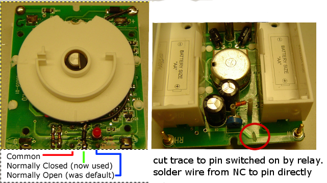
To eliminate the relay board, we have to change the behavior of the thermostat so that it turns on when it is to hot, instead of when too cold.
This was accomplished by cutting the trace on the circuit board that goes to the pin the relay switches on, and then running a wire from the relays other switching contact to that pin. (For me the pin was connected to the Normally Open side of the relay. I reconnected it to the Normally Closed side instead)
Now the thermostat circuit and the cnc4pc DC relay board inputs need to be on a low power DC circuit. For this, I tore apart an old cell phone car charger and used that as my power conversion board. All i had to do is wire the 12v power in to my main 12v DC power supply (already needed for the cooler), and then wire it through the thermostat to the inputs of the cnc4pc relay board.
The cnc4pc relay board is designed to use low power 5v inputs to switch on a heavier 12v DC load. The 12v switch works by allowing the ground to flow through it. One 12v input is connected directly to ground, and the 12v output is what switches a heavy duty car DC relay on and off by allowing its coil to find ground.
I was not able to control the cooler just with the cnc4pc relay board. The transistor on the board immediatly got super hot and the cooler would only run at 1/3 speed and was only able to draw 2.5 amps (instead of almost 5 it requires). This is why i had to use an automotive relay.
The auto relay always has its positive side of the coil live, as well as the common relay contact. The normally open contact is what sends the positive power to the female cigarette lighter plug. The negative side of this plug is directly connected to ground.
Couple post design notes:
I should probably include a 2amp fuse on the power in to the voltage converter the same as the original cell charger had.
use stand offs to space board away from mounting plate because they have the ability to get quite hot. I have used small pieces of heavy rubber tubing on the bottom side when i run the screw through the mounting hole which seems to work fine as long as proximity to heat will not be an issue.
Wood was not a good material choice for the mounting plate (fire hazard).
I didnt intend to have to use an auto relay, you may be able to skip the thermostat mod, and use the auto relay to invert the operation of the cooler, but then your 12v relay coil will be on more than off which may be a concern.
I do not know if these relays auto relays were designed to be on for 10+ minutes at a time. Will see what service life is like or if overheating becomes an issue.
You may be able to eliminate the batteries in the thermostat and power it off of the 5v power converter. it would only take one more wire and a resistor i think, but KISS is my moto on this one for now.
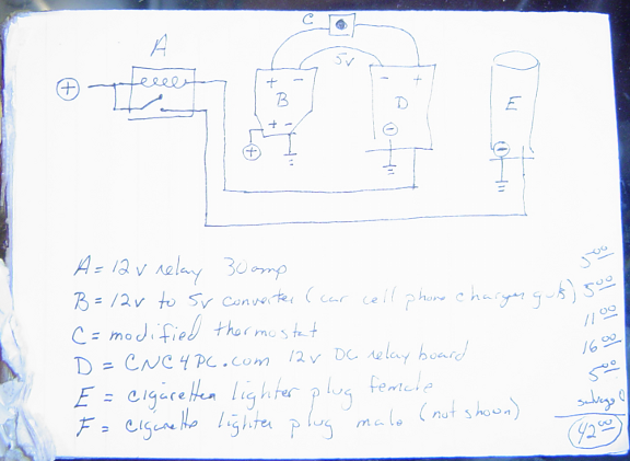
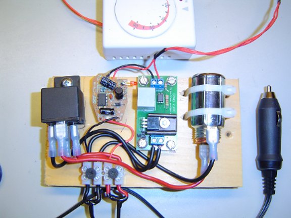
Schematic and pict of finished circuit below.
If you want to remove the cooling element for use in another project heres how. Its actually pretty easy once you see how its put together. Although it will take some persistent prying.
Remove outside fan guard - 4 screws
Remove inside fan guard. This is tricky because the plastic is very stiff. I actually smashed mine off because i was impatient but heres how. The Aluminum heatsink has two dovetail ways in its sides. The inside fanguard is designed to be slid vertically up and off. To keep it in place, the bottom lip has two small barbs that lock against the lower lip of the heatsink once it is pushed down into place. So to get it off you will have to pry both bottom sides away from one another while pulling up and not ripping your fingernails off when it finally decides to go. Or, hammer time. protect the outside fan if you go the smashum route.
insert a small pry bar into the gap between the outside heatsink and the cooler body. Slowly pry all the way around it breaking it free from the tar like adhesive that is holding the whole unit in place. The inner heatsink is the same size as the Peltier element foam encased block in the middle, so the whole thing slides out as a unit. There is no need to remove the inner heatsink and fan.
Comments: (2)
On 07.10.12 - 3:50pm Clayton wrote:
I am currently looking to hook up a peltier cooler to my humidor. I want to encase it in the humidor, allowing vent space, but at the same time I want to run it off standard batteries. Have you tried batteries with the TEC? Since I only need a 10-15 degree swing, Im curious how long the batteries would work?
On 07.10.12 - 5:07pm dave wrote:
hi Clayton
I cant really comment on how long batteries will last, I know that the unit from a power chill draws almost 5 amps. And did not run properly on less. Given a fully insulated cooler the unit ran about 50 percent of the time IE 30 minutes per hour. In an uninsulated humidor this number would have to be 100 percent
I think using a wall charger that converts to 12 V is the way to go if you have to use a battery it will have to be a car battery at least for the unit from the power chill. In the end experimentation is the only truth hope it works out for you