Trainable CNC PathsAuthor: Dave Date: 02.11.16 - 3:43am What I am experimenting with right now is a small model 2axis cnc machine (15"x9") I built using steppers and rotary encoders on each axis. 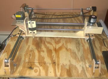
With the steppers off, I want to use an arduino to read the encoders and manually train the machine to follow a physically traced tool path. (code here) The arduino will output the results to a PC program, which will convert the readings into X,Y coordinates and output a gcode file for mach to replay. This way I can start with a physical drawing or part and go right to a tool path without having to scan, convert to svg, trace path, etc. The goal is to minimize time required to generate a path and do as much as possible on the machine. I will then hookup the model cnc machine to the stylus of my manual plasma tracer. 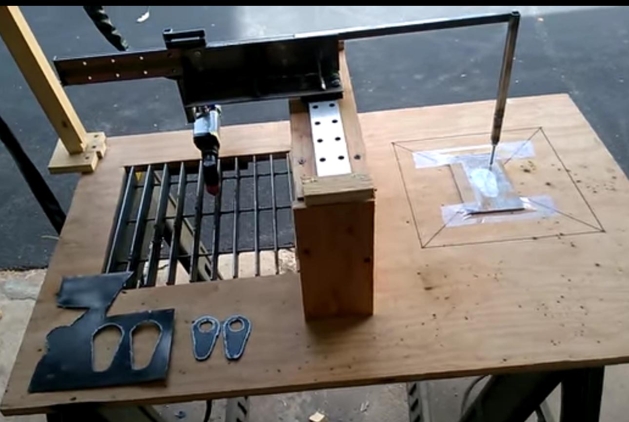
This idea came to me after doing a similar thing with a 6 axis robotic arm In terms of the hand traced path being a little jumpy because of friction in the belts and steppers or one axis moving easier than the other, this can be overcome by pushing the stylus tip against a physical template or part you are replicating. I dealt with that before with the plasma tracer. 
I also want to be able to use the setup as a make shift coordinate measuring machine. Set 0,0 on a part corner, then watch the encoders as I move it over a series of hole positions. Hit a button to record the position to a list. Then I can use the mach integration to have the machine move itself and replay the positions for hole layout in another piece without me having to really measure anything. Accuracy in this mode should be pretty good. You would be surprised how close you can get things by eye with some practice. There are also an awful lot of categories of work which do not require .001 accuracy. Realistically knowing the acceptable tolerances of what you are working on is an important key in building things efficiently. Current status - complete:
Comments: (1)On 02.16.16 - 1:26am Dave wrote:
|
About Me More Blogs Main Site
|
||||||||||||||||||||||||||