Keyless Chuck InternalsAuthor: Dave Date: 01.23.13 - 9:53pm I was always curious what the internal mechanism of a keyless chuck was. Today I had to do a tear down of one so thought i would post a pict. You should be able to zoom way in on the parts although its to dark to see the threads in each section. All teh sections were a right hand fine thread and torqued quite well. Took a vise and a giant pair of channel locks to open. One bonus is, if you have to remove a chuck like this from the spindle taper, you can disassemble it on the machine and use a puller up through the center hole. Ok i will admit it..reason its apart is I tried to drill out the center of a brand new chuck so I had a through hole for removal should the need arise. Little did I know I was drilling into the core of the mechanism! The bottom most part is what I ruined, the threaded shank looks to be peened over to hold the wider jaw base captive while still allowing some self alignment to the precise jaws. (or its a solid one piece and i removed that much metal unsure at this point although this would make more sense in hindsight.) Anyway the captive fit idea is how I am going to try to fix it which still requires some pretty careful welding. By allowing the jaw base part to float some in its capture fit, should allow for self alignment to the very precise jaw slides which would likely just bind up if I tried to weld it solid. Time will tell! And yes, I know I am a special kind of Bonehead but you just cant be afraid to experiment. How does that saying go? Its better to have experimented and lost than to never have experimented at all? :) 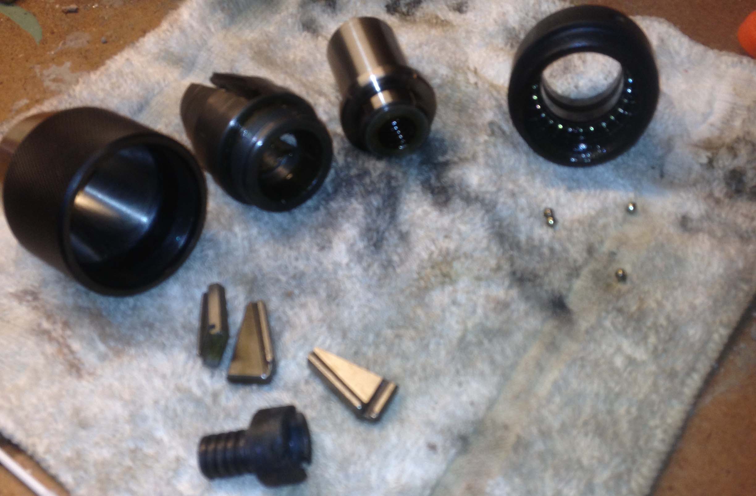
So, I really hate to throw things away, and I do kind of like projects, below is an animated GIF of the steps involved in rebuilding the center screw part to get the chuck working again. My initial guess on how much metal was missing in the first and second frame turned out to be quite far off, which lead to a fix to the fix in the others. In the end I was able to just weld it up solid which was done very carefully. I really dont think I could have pulled this off with a MIG welder. As is I used 0 filler rod when TIGing the parts together. The chuck was originally 1/32 - 5/8in capacity. With the mods to the screw it is now 0-1/2" I am happy with it although it was a lot of work and a lot of fits and test assemblies to check clearances. I will probably just use it as a tailstock chuck so I can just throw it if it ever breaks, but I have faith the repair will be really solid. 
Comments: (0) |
About Me More Blogs Main Site
|
|||||||||||||||||||