Beam TrollyAuthor: Dave Date: 02.10.13 - 4:21pm With the purchase of the new mill comes the question how do I get this into the basement. I thought of several options and I decided to take on a new project of building a small beam trolley with an electric winch so that I could easily get heavy things up and down the basement stairs all by myself. This project was completed for around $400 and probably took around 30hrs labor.
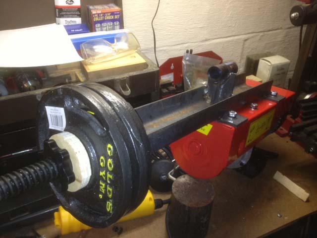
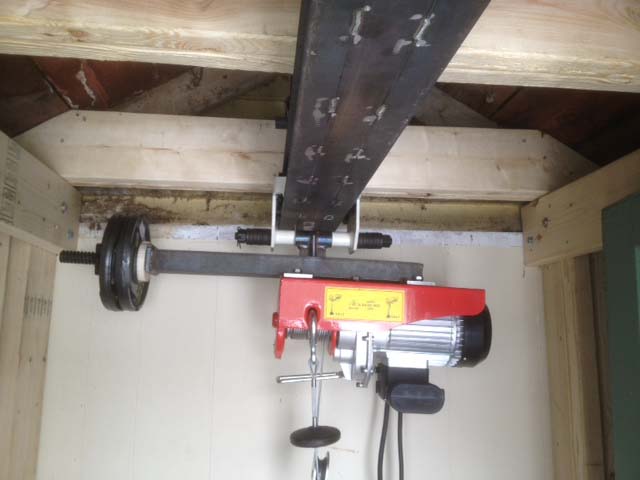
Target lifting capacity is 440 pounds with a max of 880 if I double the line over. I didnt run any numbers but from experience the design should be adequate. I will however load test the setup to make sure. You can also see how I build up the ibeam from two sections of C3 channel. I could have gotten a S3 x 7.7 ibeam for the same price as the C channel, except that I didnt like that it only had a 2.6in wide flange. Since I am going to be mounting an electric hoist on the trolly, and the hoist has about a 4in wide spool, I wanted the flange width to be at least 5in. I also had height limitations. In the first and last pict you can see the door clearance and how i had to space the new cross members up from where the old ones were. Final door to beam clearance was set at 1/2in. The beam is hanging from 12 pieces of 7/16 all thread. I bought a bag of 100 plain heavy nuts (no plating) that i welded directly to the top of the C channel. I am debating if i want to weld the jamb nuts to the mounting nuts to increase the grip on the rod. probably not in case i want to be able to dismantle it without cutting the rods. Below is a picture of how I mounted the electric hoist to the beam trolly. Now, the trolly documentation is very concerned about making sure you put the load hook exactly in the center of the trollys span and not subject it to any side loads. If you look at commercial trolly hoists they all seem to be electric chain hoists hanging from hooks. this means its a single point load directly from center, as the chain is always coming directly down off of the main cog. With an electric cable hoist, the same level of balance can not be achieved because the cable is spooled on a reel, the load center can change by up to 3in horizontally. I havent tested this design yet, and can not speak to its safety. THIS IS STRICTLY AN EXPERIMENTAL USE. The 10lbs of weights you see hanging off the end are to balance out the weight of the electric motor. You can see the fulcrum block to the right i used to balance it before i welded on the trolly mount. I set it to balance under the center of the 3in reel. the nice threaded rod is a dumbbell that i welded on. The mounting bushing itself was drilled from a piece of solid 1.25in CRS and is the right width to give the trolly proper spacing for the ibeam. It is welded on centered to the middle of the cable spool and along the center line of the hoist long wise. This means loads can be 1.5in off center left and right lengthwise, and will always be about 1in off center width wise (several thicknesses of the cable wrapped around the spool and the spools non-zero width center) which will probably just result in some pivoting of the hoist on the mounting bushing shaft. I was thinking of getting cute and welding it on in an optimized position for how much of the spool i thought would come into play, and to account where the cable came off of the spools thickness, but decided against it for simplicity and safety. (in case i my expectations didnt match reality). Had I not welded it on the centerline lengthwise, I would have had to sacrifice weld surface and creating a balanced structure for it. I also thought of modifying the spool to only hold exactly as much cable as I need, which means I could limit spool width to about 1in. This may still happen. 
Got it up and in place today and tested it out with 140lb X3 mini-mill. Worked very well. Used the line doubled over configuration just to slow down the lift, worked fine single line, but ran very fast. The misalignment of the main mount is very obvious now, my bandsaw was set and cutting perfectly square last I checked so I welded it without thinking. Turns out that was a mistake :( The cost is that the cable prefers to spool up on the downhill side noticably. I imagine this would lead to extended wear and possible damage if left to run like this. I think I will start with adding a 1/4 spacer under mounting bolts on the high side. Worst case, I will have to saws all the main mount free, shim and reweld. To much work well done to leave such a glaring flaw :- For the good news, not a single creak or groan from the beam/support structure. 
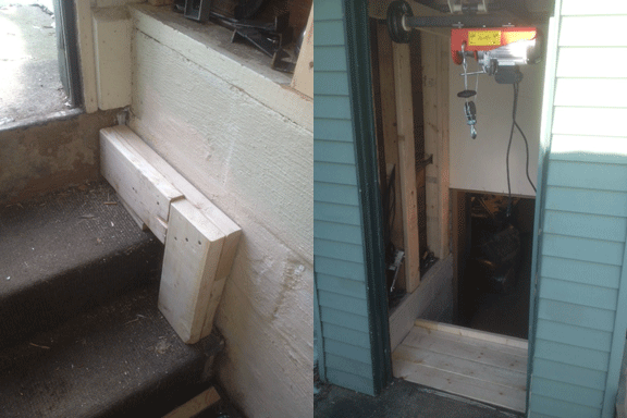
Also, since the beam doesnt extend outside the door, I built a small platform inside the stairway so I could pick things up without having to have them swing in. The hoist has been leveled by just adding a couple spacers and buying a little bit longer bolts. Should be fine. 
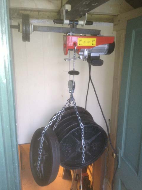
Just finished the load test using 600lbs of weights. Winch didnt even flinch not so much as a creak or groan of the structure. All welds fine, and the trolly didnt seem to mind the variable center of gravity as the wire worked across teh width of the spool. Everything seems good. 
3.12.13 - Finished re-paneling the entranceway, and just got the 400lb X3 Benchtop mill down into the basement and setup all by my self today. All the work paid off and moving went off without a hitch! Next update might be a nice smooth concrete runway from the driveway to basement entrance so I dont have to put down plywood to roll stuff, but thats for another day. Comments: (0) |
About Me More Blogs Main Site
|
|||||||||||||||||||