It is a little bit pricey at $180, but it was nice not to have to physically creat it and be able to jump right into the programming which is my primary interest. Knowing me I would have half assed building the arm anyway, so I guess it was worth it. There will be no shortage of people who would love to buy it at a bit of a discount once I fulfill my curiosity so no real loss.
So the first order of business was to create a manual controller for it. The easiest thing I could think of was to create a custom joystick that was a physical replica of the arm so that all of my motions were exactly mimicked to scale. I have completed all six axis with my model, and it is working quite nicely.
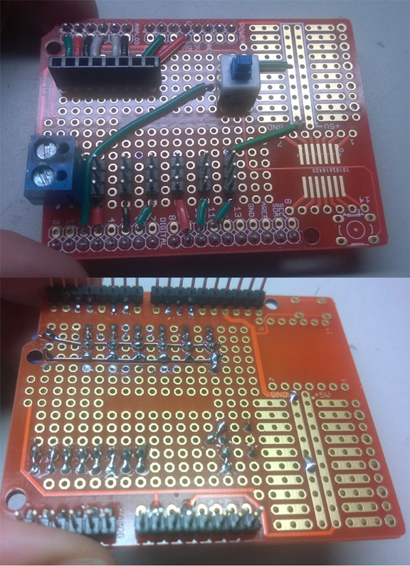
Once I passed the bread boarding stage, i decided to solder up a quick servo shield to clean up the mess of wires. The arduino has 6 PWM and 6 Analog inputs so it works out just right. I still have to add a gripper though, which is going to demand one more of each. I can either ignore one of the arms joints and add a gripper, or what I will probably do is just piggy back an ATTiny onto the board and have that control the last input, but humm how to control that in replay mode? Maybe I will have to upgrade to either a servo shield or a Mega :-
so far I have about ten hours into the project which really is nothing for the complexity of what it is doing.
next I created a Windows application that will log of the serial output and can replay it back to the controller. In this way I can program the arm through the joystick, and have his actions repeatable. This took another couple hours of tinkering. Right now I am capturing/replaying position only. I still need to add timestamps, and then honor those in the replay. This should be pretty easy at this point though.
Next..humm maybe some position and repeat-ability tests, then I can move on into adding a camera and object detection! Also using 2 cameras (one over top and one to the side) maybe I can super impose a Cartesian corrodinate system and have the arm seek coordinates from the cameras view of its position. (Think warmer/colder game from childhood)
Well i ended up returning the arm after less than a week.
Pros:
comes fully assembled saving a lot of time
ascetically pleasing and decent construction
capable of complex positioning and full 6 axis movement
Cons: (Deal breakers)
the two micro servos at the end of the arm are very weak
arm end can not be easily modified (brackets glued to tube)
no suitably lite weight gripper attached could be found
no real vendor code or instructions
For $180, you really want something you can directly use without having to screw around. In particular you need a suitable gripper end and strong enough servos out there to make use of it.
I also ended up finding another fully assembled clone of this on ebay, but made of stainless steel for 80 dollars cheaper. I dont think I will bother with that one either though since it still has the micro servos on the end and no gripper.
Comments: (9)
On 04.28.16 - 8:29am fimdomeio wrote:
I just got mine today.
Just to let you know that the uarm vacuum griper works pretty well with this arm. just had to enlarge two holes a little bit and without further modifications the gripper stays a little offcenter. to me thats not really a problem.
Also a question. Did your end of the arm (after the pvc) also came loose? I mean... the oly thing that prevents mine from falling are the cables.
On 04.28.16 - 8:43am Dave wrote:
the end of the arm looks to be glued securely to the end of pvc tube on mine. Thanks for the tip on the vacuum gripper!
On 02.16.17 - 2:28am Dave wrote:
>Can you please show me how to connect the wiring connections?
Hi, I am afraid I dont have an in depth write up on the wiring itself.
basically all of the potentiometers share a common power and ground. Then each pots wiper is connected to a different analog port on the arduino uno (A0-A5) to read its position. In the first shield picture this is the female header strip at the top, with the first two on the right being the power and ground connections to the joystick.
The servos take 3 wires each. All of the servo connections on the sheild are the male pins in groups of 3. The blue power block you see takes the 12v DC from the power supply and is shared across all of the servo groups. You can see a 2 solid wires used as a power and ground bus on the shot from the underside of the board. Each servo also gets its own PWM signal port from the arduino which controls its position. The button you see in the shield close up is toggle the code between running in joystick or replay mode (covered in another video)
You can find a link to the code in the blog post mentioned above. All of the pins used are defined at the top of the source and commented on what they are. You want to look at /controller/controller.ino
You can also wet your feet and experiment with the simplified code in /servo_limits/servo_limits.ino
to get a handle on controlling a single servo from a single pot.
Hope that helps. Good luck with your project.
On 02.21.17 - 12:24am Peter wrote:
Hi,
Excellent project! Its nice you show also your thoughts and failures in your video, before you get it to work right.
I want to build a similar robot controller and have some questions about the joints/hinges.
Did you use anything else than screws and nuts? At the joints which have potentiometers, do you use the pots directly as joints or do you have anything else to support/stabilize it? I especially wonder how the pot at the base can support the weight.
If you could post some close up of the joints so you can see how it works, Id appreciate it )
On 02.21.17 - 9:56pm Dave wrote:
Hi peter,
Thanks for the interest in the project. Afraid I already gave the joystick away to another enthusiast so cant take any more Picts. The pots were used as the primary joint pivot material without any additional stabilization. The hole in each piece was drilled very closely to size. The pot screws tightly into one side and then the pot body is hot glued to that side, on the other side the pot dial shaft is press fit and hot glued. The arm is made of all thin pieces of hardwood to minimize weight. The pots seem to handle this light duty task quite well . All other parts are joined with hot glue only or a screw and nut where non metered pivot joint is needed. Hope that helps have fun with your project.
On 02.22.17 - 4:44pm Peter wrote:
Thanks!
Do you happen to remember the pot model? (I usually have only small breadboard pots and would like to get a reliable one for this use case.)
On 02.22.17 - 5:12pm Dave wrote:
I used a 10k linear taper pot, k value isnt that important but linear is a must I think. The Amazon part number of the ones I used is B00DN7MSXY but they dont look available at the moment. I think they are a pretty standard style and quality
On 02.22.17 - 5:37pm Dave wrote:
I used a 10k linear taper pot, k value isnt that important but linear is a must I think. The Amazon part number of the ones I used is B00DN7MSXY but they dont look available at the moment. I think they are a pretty standard style and quality
On 04.09.17 - 5:27am Anonymous wrote:
Rahul asks:
Thank you so much. I have worked on it, but the replay is very slow. Can you please suggest a solution for the slow replay.
Response:
you can speed up the replay by using a slower sample rate (add a delay between when the sample points are taken) this will have the side effect of making the motion more jumpy. Is your replay slower than what is shown in the video? The default replay rate did not seem to bad for me in testing. Look at my other video on cnc path training to see what I thought was slow. There are two bottle necks possible..one we are asking the poor arduino to do csv value string processing to get all 6 joints corridinates and we are using the string template library. You could also optimize this. You could also record the positions of less joints which would speed it up. You could port this to a faster microcontroller. The second bottle neck is that all data is being passed over the serial port as a text string. You could try increasing the baud rate. You could experiment with some kind of minimal data compression library to send compressed binary data over the serial and decompress on the arduino to further test this as a bottle neck...although then you will be further taxing the arduino processing speed to decompress it. The easiest things are to try to up the baud rate on teh serial line, record less joints, and decrease the sample rate. There is also the chance there is a bug..on the windows app side I had just added a feature to record the timestamp so that if you paused the arm while recording..it would mimic the pause..you can disable that too and see if that was causing a problem. I think you would should be able to get it as fast as you need without much work.